Municipal wastewater treatment plants
Purpose
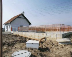
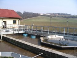
ADOS municipal Waste Water Treatment Plants are complex and compact large-scale systems intended for exacting Wastewater treatment of amounts. They serve for wastewater treatment from conurbation, large factories, separated villages, catchment areas. Based on long-lasting pieces of experience got from planning and erection of Waste Water Treatment Plants in our homeland and abroad ADOS Co. has developed these treatment plants to meet the demanding conditions of ecological criteria and requirements of customers
Design Description
In one tank an integrated reactor of our design combines all decisive processes of wastewater treatment and a biological sludge pre-thickener also makes an integral part of it. Compact design of the units of main technology minimises inside circuits, a bay of the wastewater treatment plant and enables an architectural situation in landscape.
Mechanical Pre-treatment
Trash racks, manually or mechanically racked, and rotary screens and similar facilities are used to remove first big mechanical debris from wastewater flowing in a fore denitrification zone.
De-nitrification Zone
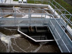
Denitrification mix has to be maintained floating – pneumatic or with an electrically-driven agitators are applied for stirring. If need be to support nitrification effect (e.g. during winter season) an aeration system with an independent valve is installed.
De-nitrification mix flows through an opening in a partition from the denitrification zone to the nitrification one.
Nitrification Zone
Aeration system uses Roots blowers provided with a speed change-over-switch and aeration distribution system all manufactured of rust-resistant steel. The aeration system is installed on the bottom and uses fine bubbles system that keep the activated mix floating. The aeration system described above meets even the most challenging requirements for efficiency of oxygen transfer as well as demands of operational economy and reliability.
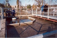
Final Settling Zone - Separation USBF
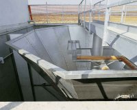
Final settling tank USBF divides the unit capacity in separate process zones interconnected in closed circulation loops. As to the design shape both a circular and rectangular shapes can be used.
Final settling zone USBF can be of a different shape – conical or triangular prism. A part of circulating activated sludge mix and treated water flow in this zone where they are separated, settled and activated sludge is made thicker.
The bottom of the final settling zone USBF is provided with a piping through which sludge required is pneumatically pumped back to the denitrification zone (sludge recirculation)..
Effluent flows out through a collecting discharge trough, adjustable in height, provided with scumboards that prevent fine particles flowing out.
Sludge Handling
An age of Sludge of the technology supplied makes more than 26 days. This age guarantees full aerobic stabilisation. Since polluted wastewater continuously flows in the treatment plant then an excess sludge has to be pumped out from the system after reaching an operational activated sludge concentration.
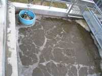
Sludge handling is designed with respect to the daily production of excess sludge. The wastewater treatment plants use special sludge pre-thickener of type PZK that enables to make the sludge thicker having 3 – 4 % of dry matter. Aerobically stabilised sludge thickened in this way enables easy its handling and further processing (e.g. automatic sludge thickener, decantation centrifugal separator, Frame filter press or box filter press, … ).
Effluent
Effluent is of such quality that it can directly enter a recipient – river flow.
In case of water recycling the process can be provided with a tertiary final treatment with a drum micro-screen in combination with chemical precipitation of phosphorus and water disinfection. It guarantees an excellent water quality as to undissolved matters, residual organic substances, nitrogen pollution and phosphorus are concerned (see Table).
| BOD | [mg/l] | 10-20 |
| COD | [mg/l] | 70-110 |
| SS | [mg/l] | 15-20 |
| N-NH4 | [mg/l] | 2-5 |
| Ntot | [mg/l] | 15-25 |
| Ptot | [mg/l] | 1-3 |
Separation
|
Activation
|
Pre-thickener
|
Technological schema
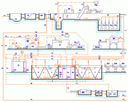
Technological schema
|
Layout in landscape
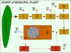
Shema WWTP
|
Legend:
1. Trap of carried along debris A. Separated coarse debris
2. Trash racks (manually or mechanically racked) B. Separated coarse debris
3. Fine screen mechanically racked C. Separated fine particles
4. Sand D. Separated grit
4a.Sand washing machine E. Effluent from reactor
5. Rotary drum screen F. Excess biological sludge
6. Biological reactor
7. Sludge pre-thickener
8. Sludge bin
9. Sludge dewatering


